| Model: | P7 |
|---|---|
| Function: | 1. Step and trench depth measurement within the allowable range of the probe; 2. Thickness measurement of various deposited thin films; 3. Surface roughness measurement. |
| Engineer: | Qu; Fu / +86-21- 34207734-8003 / 34206126-6010 / minni.qu@1; xuecheng.f@1 |
| Location: | East Area – Testing III, West Area – Thin Film IA |
| Equipment ID: | EFM3SP701、WF1KSPR01 |
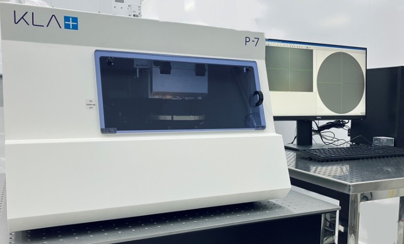
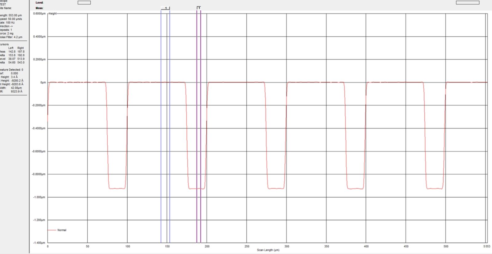
It is mainly used for the depth measurement of steps and trenches. It features high measurement accuracy and good repeatability, and can be applied to the thickness testing of organic thin films.
Process/Testing Capabilities
It can be used to measure step height, thin film surface roughness and other parameters, covering the characterization of thin films and patterns in various technological processes including semiconductor wet processing, lithography patterning, thin film growth and etching, as well as packaging.
Technical Specifications
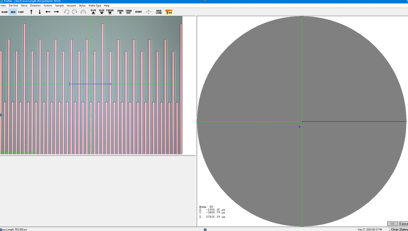
2. The size of test samples shall be less than 6 inches.
3. The step height of test samples shall be less than 1000 μm.
(2) When loading or unloading samples, only the sample stage and front window are allowed to be touched; contact with any other internal parts of the equipment is prohibited.
(3) When lowering the probe under the "Focus" function, if the operator anticipates emergency risks such as probe position deviation or probe collision, immediately press the Esc key on the keyboard to stop the probe descent.
(4) When scanning the edge of the sample, set the scanning direction from the inside of the sample toward the outer edge; avoid starting the scan from a suspended position.
(5) When the step height is greater than 50 μm, scan downward from the upper side of the step to the lower side.
(6) If it is necessary to measure samples that are thinner, thicker, larger, smaller, or extremely uneven compared with standard 3–6 inch wafers, please contact the process person in charge for assistance.
(7) In case of software error prompts during operation, take a screenshot for timely preservation and contact the process person in charge.
The interlock is triggered, causing the system to automatically cut off the software's control over the moving parts.
Troubleshooting Methods
(1) Check whether the front window is properly closed. Open and gently close the front window again, then try moving the sample stage once more.
(2) Check whether the front, rear, left and right panels of the equipment are loose. Contact the process person in charge if any looseness is found.
(3) If the above operations fail to resolve the fault, please contact the process person in charge.

Address: 800 Dongchuan Road, Minhang District, Shanghai 200240, China
Tel: +86 21 3420 7734
Email: [email protected]